- 您现在的位置:买卖IC网 > Sheet目录342 > MCBSTM32EXL (Keil)BOARD EVALUATION FOR STM32F103ZE
�� �
�
�Independent� watchdog� (IWDG)�
�RM0008�
�17.3.1�
�17.3.2�
�17.3.3�
�Hardware� watchdog�
�If� the� “Hardware� watchdog”� feature� is� enabled� through� the� device� option� bits,� the� watchdog�
�is� automatically� enabled� at� power-on,� and� will� generate� a� reset� unless� the� Key� register� is�
�written� by� the� software� before� the� counter� reaches� end� of� count.�
�Register� access� protection�
�Write� access� to� the� IWDG_PR� and� IWDG_RLR� registers� is� protected.� To� modify� them,� you�
�must� first� write� the� code� 0x5555� in� the� IWDG_KR� register.� A� write� access� to� this� register�
�with� a� different� value� will� break� the� sequence� and� register� access� will� be� protected� again.�
�This� implies� that� it� is� the� case� of� the� reload� operation� (writing� 0xAAAA).�
�A� status� register� is� available� to� indicate� that� an� update� of� the� prescaler� or� the� down-counter�
�reload� value� is� on� going.�
�Debug� mode�
�When� the� microcontroller� enters� debug� mode� (Cortex-M3� core� halted),� the� IWDG� counter�
�either� continues� to� work� normally� or� stops,� depending� on� DBG_IWDG_STOP� configuration�
�bit� in� DBG� module.� For� more� details,� refer� to� Section� 29.16.2:� Debug� support� for� timers,�
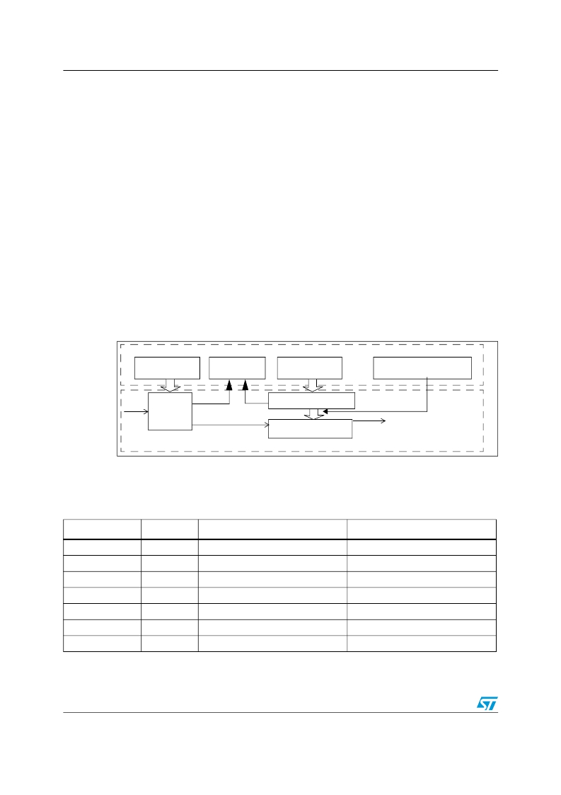
��Figure� 158.� Independent� watchdog� block� diagram�
�1.8� V� voltage� domain�
�Prescaler� register�
�IWDG_PR�
�8-bit�
�LSI�
�(40� kHz)� prescaler�
�Status� register�
�IWDG_SR�
�Reload� register�
�IWDG_RLR�
�12-bit� reload� value�
�Key� register�
�IWDG_KR�
�IWDG� RESET�
�12-bit� downcounter�
�V� DD� voltage� domain�
�Note:�
�Table� 81.�
�The� watchdog� function� is� implemented� in� the� V� DD� voltage� domain� that� is� still� functional� in�
�Stop� and� Standby� modes.�
�Watchdog� timeout� period� (with� 40� kHz� input� clock)Min/max� IWDG� timeout�
�period� at� 32� kHz� (LSI)� (1)�
�Prescaler� divider�
�/4�
�/8�
�/16�
�/32�
�/64�
�/128�
�/256�
�PR[2:0]� bits�
�0�
�1�
�2�
�3�
�4�
�5�
�6� (or� 7)�
�Min� timeout� (ms)� RL[11:0]=� 0x000�
�0.1�
�0.2�
�0.4�
�0.8�
�1.6�
�3.2�
�6.4�
�Max� timeout� (ms)� RL[11:0]=� 0xFFF�
�409.6�
�819.2�
�1638.4�
�3276.8�
�6553.6�
�13107.2�
�26214.4�
�1.� These� timings� are� given� for� a� 40� kHz� clock� but� the� microcontroller’s� internal� RC� frequency� can� vary� from� 30� to� 60� kHz.�
�Moreover,� given� an� exact� RC� oscillator� frequency,� the� exact� timings� still� depend� on� the� phasing� of� the� APB� interface� clock�
�versus� the� LSI� clock� so� that� there� is� always� a� full� RC� period� of� uncertainty.�
�400/995�
�Doc� ID� 13902� Rev� 9�
�发布紧急采购,3分钟左右您将得到回复。
相关PDF资料
MCBTMPM330
BOARD EVAL TOSHIBA TMPM330 SER
MCIMX25WPDKJ
KIT DEVELOPMENT WINCE IMX25
MCIMX53-START-R
KIT DEVELOPMENT I.MX53
MCM69C432TQ20
IC CAM 1MB 50MHZ 100LQFP
MCP1401T-E/OT
IC MOSFET DRVR INV 500MA SOT23-5
MCP1403T-E/MF
IC MOSFET DRIVER 4.5A DUAL 8DFN
MCP1406-E/SN
IC MOSFET DVR 6A 8SOIC
MCP14628T-E/MF
IC MOSFET DVR 2A SYNC BUCK 8-DFN
相关代理商/技术参数
MCBSTM32EXLU
功能描述:开发板和工具包 - ARM EVAL BOARD + ULINK2 FOR STM32F103ZG
RoHS:否 制造商:Arduino 产品:Development Boards 工具用于评估:ATSAM3X8EA-AU 核心:ARM Cortex M3 接口类型:DAC, ICSP, JTAG, UART, USB 工作电源电压:3.3 V
MCBSTM32EXLU-ED
制造商:ARM Ltd 功能描述:KEIL STM STM32EXL EVAL BOARD
MCBSTM32EXLUME
功能描述:开发板和工具包 - ARM EVAL BOARD + ULINKME FOR STM32F103ZG
RoHS:否 制造商:Arduino 产品:Development Boards 工具用于评估:ATSAM3X8EA-AU 核心:ARM Cortex M3 接口类型:DAC, ICSP, JTAG, UART, USB 工作电源电压:3.3 V
MCBSTM32F200
功能描述:开发板和工具包 - ARM EVAL BOARD FOR STM STM32F207IG
RoHS:否 制造商:Arduino 产品:Development Boards 工具用于评估:ATSAM3X8EA-AU 核心:ARM Cortex M3 接口类型:DAC, ICSP, JTAG, UART, USB 工作电源电压:3.3 V
MCBSTM32F200U
功能描述:开发板和工具包 - ARM EVAL BOARD FOR STM STM32F207IG + ULINK2
RoHS:否 制造商:Arduino 产品:Development Boards 工具用于评估:ATSAM3X8EA-AU 核心:ARM Cortex M3 接口类型:DAC, ICSP, JTAG, UART, USB 工作电源电压:3.3 V
MCBSTM32F200UME
功能描述:开发板和工具包 - ARM EVAL BOARD FOR STM STM32F207IG ULINK-ME
RoHS:否 制造商:Arduino 产品:Development Boards 工具用于评估:ATSAM3X8EA-AU 核心:ARM Cortex M3 接口类型:DAC, ICSP, JTAG, UART, USB 工作电源电压:3.3 V
MCBSTM32F200UME-ED
制造商:ARM Ltd 功能描述:KEIL STM32F207IG EVAL BOARD
MCBSTM32F400
功能描述:开发板和工具包 - ARM EVAL BOARD FOR STM STM32F407IG
RoHS:否 制造商:Arduino 产品:Development Boards 工具用于评估:ATSAM3X8EA-AU 核心:ARM Cortex M3 接口类型:DAC, ICSP, JTAG, UART, USB 工作电源电压:3.3 V